Plunge Basin Examples: Difference between revisions
From ASDSO Dam Safety Toolbox
No edit summary |
No edit summary |
||
| Line 2: | Line 2: | ||
<gallery mode="slideshow"> | <gallery mode="slideshow"> | ||
File:plunge basin.jpg|Unlined plunge basin (view is looking downstream). This basin has been allowed to scour over time. | File:plunge basin.jpg| link= |Unlined plunge basin (view is looking downstream). This basin has been allowed to scour over time. | ||
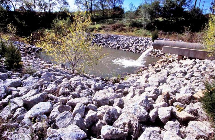
File:riprap plunge basin.jpg|A riprap-lined plunge basin. | |||
File:concrete plunge basin.jpg|link=|Concrete-lined plunge basin with baffle wall, grouted riprap side slopes, and discharge channel. Flow discharges into the plunge basin from two 36-inch diameter fixed-cone valve. | File:concrete plunge basin.jpg|link=|Concrete-lined plunge basin with baffle wall, grouted riprap side slopes, and discharge channel. Flow discharges into the plunge basin from two 36-inch diameter fixed-cone valve. | ||
File:typical plan.jpg|link=|Plan view of a typical lined plunge basin design. | File:typical plan.jpg|link=|Plan view of a typical lined plunge basin design. | ||
</gallery> | </gallery> | ||
[[File:riprap plunge basin.jpg]] | |||
Revision as of 17:31, 6 June 2022
When the erosion anticipated downstream of the outlet works is minimal and/or manageable, a plunge basin (pool) is commonly used as the energy dissipator. Plunge basins may be lined or unlined. The discharge into the basin may come from a free outlet or from a valve. The following pictures are examples of plunge basins:


