
Pre-Modeling Communication: Slope Stability Model Considerations
From ASDSO Dam Safety Toolbox
|
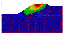
| Example of a slope stability analysis.
(Image Source: Wikipedia) |
Prior to performing a slope stability analysis, the following modeling parameters and key assumptions should be considered and addressed in a model work plan as appropriate:
- State the software selection and describe the limitations of the program as they apply to this project.
- State whether a two-dimensional or three-dimensional model will be used. Consider a phased approach if there is uncertainty whether the problem warrants a two-dimensional or three-dimensional model. Document reasons for this uncertainty.
- Describe the basis for material parameters to be selected. Summarize existing materials and new materials.
- Note the sources of information and describe the uncertainties or limitations of that information.
- If a parametric sensitivity analysis is planned, describe the approach.
- Note the minimum factors of safety or other performance criteria.
- If seismic analysis is planned, describe the approach for analysis (e.g., pseudo-static, minimum factor of safety, deformation based) and materials (residual strengths).
- Describe the approach for developing the section geometry and pore pressure assignment (flow net, phreatic or potentiometric surfaces) including the source of information and the uncertainties or limitations that could impact results. Is a seepage model needed and useful or can a reasonable phreatic surface(s) and pore pressure gradients (e.g., adjusting unit weight of water to account for downward drainage) be assumed? Should a range of pore pressure assumptions be analyzed and presented to determine sensitivity to this assumption?
- Describe the decision process for selecting the number of cross sections chosen for analysis. One cross section may be enough, but more than one section may be needed depending on conditions and geometry. Reviewers often want to know what was considered but will not be used.
- Describe how potential failure surfaces will be determined. Justify with information specific to the dam and problem to be determined. For example, if deciding to use a particular point and radius search pattern to determine the critical failure surface, explain why this is appropriate. Consider including specified failure surfaces.
- Describe uncertainties with laboratory testing with potential impact on failure surfaces. For example, if using index testing to estimate strength parameters of a material that contains likely failure surfaces, what is the impact? Would it be appropriate to perform sensitivity analyses to bracket the potential range of response for materials where strength parameters are less certain?
- Consider including one or more rough cross-sectional drawings that illustrate dam geometry, materials, reservoir water surface(s) to be modeled with estimated phreatic and potentiometric water surfaces that correspond to these reservoir levels. A hand drawing may be acceptable. If a berm or other stabilizing structure is to be added, include rough dimensions of this structure on this drawing. Show location of boreholes, piezometers, and interpreted material types/boundaries. Note piezometer influence zones (perforated intervals plus gravel pack) and measured water levels that correspond with the reservoir water surfaces on the drawing. Note location of laboratory test samples on this drawing. Graphical presentation of this information is an important communication aid, particularly for less technical readers. Vertical exaggeration may be helpful to show small vertical differences, but should be used with caution.
Development of this page was sponsored by the Montana Department of Natural Resources & Conservation with funding from the FEMA Assistance to States Grant Program.
Revision ID: 8030
Revision Date: 08/27/2024