
Pre-Modeling Communication: Seepage Model Considerations
From ASDSO Dam Safety Toolbox
|
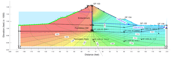
| Seepage analysis of embankment dam (Photo Source: Gannett Fleming). |
Prior to performing a seepage analysis, the following modeling parameters and key assumptions should be considered and addressed in a model work plan as appropriate:
- State the software selection and describe the limitations of the program as they apply to this project.
- State whether a steady state or transient model will be used. Consider a phased approach if there is uncertainty whether the problem warrants a steady-state or transient model. Document reasons for this uncertainty.
- State whether a two-dimensional or three-dimensional model will be used. Consider a phased approach if there is uncertainty whether the problem warrants a two-dimensional or three-dimensional model. Document reasons for this uncertainty.
- State basis for boundary conditions that will be used and uncertainties or limitations of those boundary conditions versus the site conditions.
- Describe the basis for material parameters to be selected. Summarize existing materials and new materials. If unsaturated materials are used, describe the approach for developing volumetric water content and hydraulic conductivity functions.
- Note the sources of information and describe the uncertainties or limitations of that information.
- If a parametric sensitivity analysis is planned, describe the approach.
- Describe the calibration approach. If piezometers are used for calibration, provide detailed descriptions of the available information and the metrics to be used for evaluation of model calibration (average percent error across the system for ballpark seepage quantity versus spatial considerations for use in stability analyses and evaluation of more localized seepage issues).
- Consider including one or more rough cross-sectional drawings that illustrates dam geometry, foundation, materials, reservoir water surface(s) to be modeled, along with estimated phreatic and potentiometric water surfaces from piezometer measurements. A hand drawing may be acceptable. If additional drainage features are to be evaluated, show the approximate location of these features. Show location of boreholes and piezometers. Note piezometer influence zones (perforated intervals plus gravel pack) and measured water levels that correspond with the water surfaces on the drawing. Graphical presentation of this information is an important communication aid, particularly for less technical readers. Vertical exaggeration may be helpful if small vertical differences need to be highlighted.
Development of this page was sponsored by the Montana Department of Natural Resources & Conservation with funding from the FEMA Assistance to States Grant Program.
Revision ID: 8025
Revision Date: 08/06/2024